ECE243 Final Review
This Review supplements the weekly lecture materials. In addition to this Review, it is recommended to read the other weekly lecture slides. An aid sheet is attached at the bottom
Floating Point
Floating point refers to the binary representation of decimal numbers. Note that in most cases, floating point storage is only an approximation of the real number — for example, the infinite decimal 1/3 cannot be accurately represented in floating point.
IEEE 754 Conversion
Will supplement later. If you don't want to learn it, just use the calculator: https://www.h-schmidt.net/FloatConverter/IEEE754.html
Coding Tips
Program Termination
Unless otherwise specified, every program should end with an infinite loop
a. END: MOV PC, END (not recommended — see "Three ways to load an address into a register". If this is a very large program and this line of code appears at address 257, meaning END represents the address 257, what happens at compile time?)
b. END: B END (simple and easy to use)
( Q: What happens if you don't add this? A: "Instruction fetched from a location outside of a code section (.text or .exceptions)." Every program consists of different segments. Each executable ELF has headers specifying the start and end addresses of each segment. When an address outside .text enters PC, the debugger reports the above error.
Definition of each segment
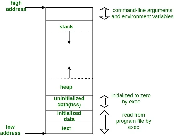 (Source: GeeksforGeeks, Memory Layout of C Programs)
)
Three Ways to Load an Address into a Register
a. MOV R0, #0x10 (not recommended) Strongly not recommended to use the MOV instruction on numbers larger than one byte (8 binary bits). In most cases, you'll get a compile-time error saying the number can't be encoded into the opcode.
b. Use MOVT and MOVW together (Monitor Program's compiler default method) MOVT stands for MOV Top — fills a value smaller than 16 bits into the top half of the register (top, bits 31-16) MOVW stands for MOV Wide — fills a value smaller than 16 bits into the bottom half of the register (wide, bits 15-0) Example: Load the DE1-SoC switch (SW) address (0xff200040) into R0 register
MOVW R0, #0x0040
MOVT R0, #0xff20
Exercise: If R0 contains 0xffffffff, what is R0 after immediately executing the following instruction?
MOVW R0, #0xaaaa
c. Use LDR (pseudo instruction, simple and easy to use — most recommended for exams)
LDR R0, =0xff200040
Note: no # symbol. This instruction can't be directly converted to a single word opcode. The basic principle is to place the word 0xff200040 at an address some "offset" below this line of code, then use LDR to load the word at pc+offset.
I/O Devices
Covered in detail in the DE1-SoC Hardware post
This section only covers the VGA Controller, which was not fully covered previously
VGA (Video Graphics Array) Controller
A 2D-Array that displays images by writing colors to 320x240 pixels. [In fact, the DE1-SoC board also supports a 1D-Array mode, drawing from the top-left pixel (index=0) all the way to the bottom-right pixel (index=76799). As far as I know, this isn't covered in class, but if a question specifies setting the A bit in the Status Register (0xFF20302C, see "DE1-SoC VGA Controller: Pixel buffer controller registers" below) to 1, then you should use this mode.]
Colors
| Bits | 15:11 | 10:5 | 4:0 |
|---|---|---|---|
| Color | Red | Green | Blue |
Each pixel uses 16 bits, i.e. one halfword, i.e. two bytes, i.e. occupies two addresses
(See below — why is Bit 0 of the pixel address offset always 0?)
We know any color can be composed from the optical primary colors (Red, Green, Blue; RGB).
Method: Adjust the brightness of each color component
For the DE1-SoC color encoding, we can see:
| Bits | 15:11 | 10:5 | 4:0 |
|---|---|---|---|
| Color | Red | Green | Blue |
| Number for 100% Brightness | 2^5 = 32 | 2^6 = 64 | 2^5 = 32 |
From this we can see that on the DE1-SoC board, green has higher adjustable precision than red and blue.
Addresses (Method 1: Without Pixel Buffer Controller — not recommended. After reading this section, use Method 2)
The CPU speed doesn't match VGA display speed. Without the Pixel Buffer Controller, writing directly to the screen easily causes flickering.
Each pixel has its own address:
Some Pixel's Address = Base Address + This Pixel's Address Offset
Direct display Base Address = 0xc8000000
Offset (Formula = 2x + 1024y): Remember that multiplying by a power of 2 is a left Bit Shift
| Bits | 31:18 | 17:10 | 9:1 | 0 |
|---|---|---|---|---|
| Function | 0 | y [7:0] | x [8:0] | 0 |
Definition of each bit in the address
Hands-on: How to display a funky color at position (x=2, y=2)
A funky color picked from the Windows Paint color palette
| Color | Red | Green | Blue |
|---|---|---|---|
| % Brightness | 20/255 | 198/255 | 211/255 |
| 100% Brightness on DE1-SoC | 32 | 64 | 32 |
| Brightness on DE1-SoC in Decimal | 32*20/255 = 3 | 64*198/255 = 50 | 32*211/255 = 26 |
| Brightness on DE1-SoC in Binary | 0b11 | 0b110010 | 0b11010 |
| Complete Halfword (binary) | 0b00011, 110010, 11010 |
Color calculation
| Bits | 31:18 | 17:10 | 9:1 | 0 |
|---|---|---|---|---|
| Position | 0 | Y = 2 | X = 2 | 0 |
| Position in binary | 0 | 0b10 | 0b10 | 0 |
| Offset | 0b0000001000000010 0 |
Address Offset calculation
ARM code:
ldr r7, =0xc8000000  // base
ldr r1, =0b100000000100  // offset
ldr r0, =0b0001111001011010  // color
strh r0, [r7, r1]  // store as half-word
C code:
volatile int VGA_base = 0xc8000000;
int offset = 0b100000000100;
short color = 0b0001111001011010;
*(short *)(VGA_base + offset) = color;
STRH and (short*) are important: you must store as a halfword, otherwise the adjacent pixel will turn black
(i.e. if we write a full word to that address: 0b 0000 0000 0000 0000 0001 1110 0101 1010
the target pixel gets the halfword 0b 0001 1110 0101 1010, turning into the funky color
the adjacent pixel gets the halfword 0b 0000 0000 0000 0000, turning black)
Addresses (Method 2: Using Pixel Buffer Controller — no flickering)
DE1-SoC VGA Controller: Pixel buffer controller registers
Buffer Register and Backbuffer Register each hold a different address. The DMA controller reads pixel colors starting from the front buffer address in the Buffer Register, writing to the screen until the bottom-right pixel is drawn. At that point, the S bit in the Status Register is set to 0. Writing 1 to the Buffer Register (the address it holds doesn't change, but S in the Status Register immediately becomes 1) triggers a swap between the Buffer Register and Backbuffer Register contents — the original Backbuffer address moves to the Buffer, and the original Buffer address moves to the Backbuffer. The swap doesn't happen immediately after writing 1 — it only occurs after the buffer content at the Buffer Register's address is fully drawn to the screen. In other words, as long as the bottom-right pixel on the screen hasn't been drawn yet, the two addresses won't swap. This waiting time is 1/60 second, the well-known Vertical Synchronization Time (VSync — you'd know if you play games).
Example: C code
////////////////////////////Haven't written it yet, will publish when done
C Code
After reading the VGA examples thoroughly, combined with the basics from 105, that should be sufficient. Some additional topics for potential short-answer questions:
Volatile (as a qualifier): Volatile tells the compiler not to optimize anything that has to do with the volatile variable. It can't remove the memory assignments, it can't cache variables and it can't change the order of assignments either.
Interrupts
- Hardware interrupt DE1-SoC Hardware
- Software Interrupt (appeared in past exams, not tested last year — comment if you want to see it)
Aid Sheet (2019)
Recommended Sections:
- Various LDR syntax usage
- Various SUB syntax usage
- Understanding PC (small text on the bottom right of front page)
- Common data tables, hex-display patterns (right side of front page)