This is a small project done in the summer as my elementary approach to learn Python, and the “gpiozero” library for controlling GPIO devices on a Raspberry Pi.
The panel can display hexadecimal numbers/letter from 0x0-0xf.
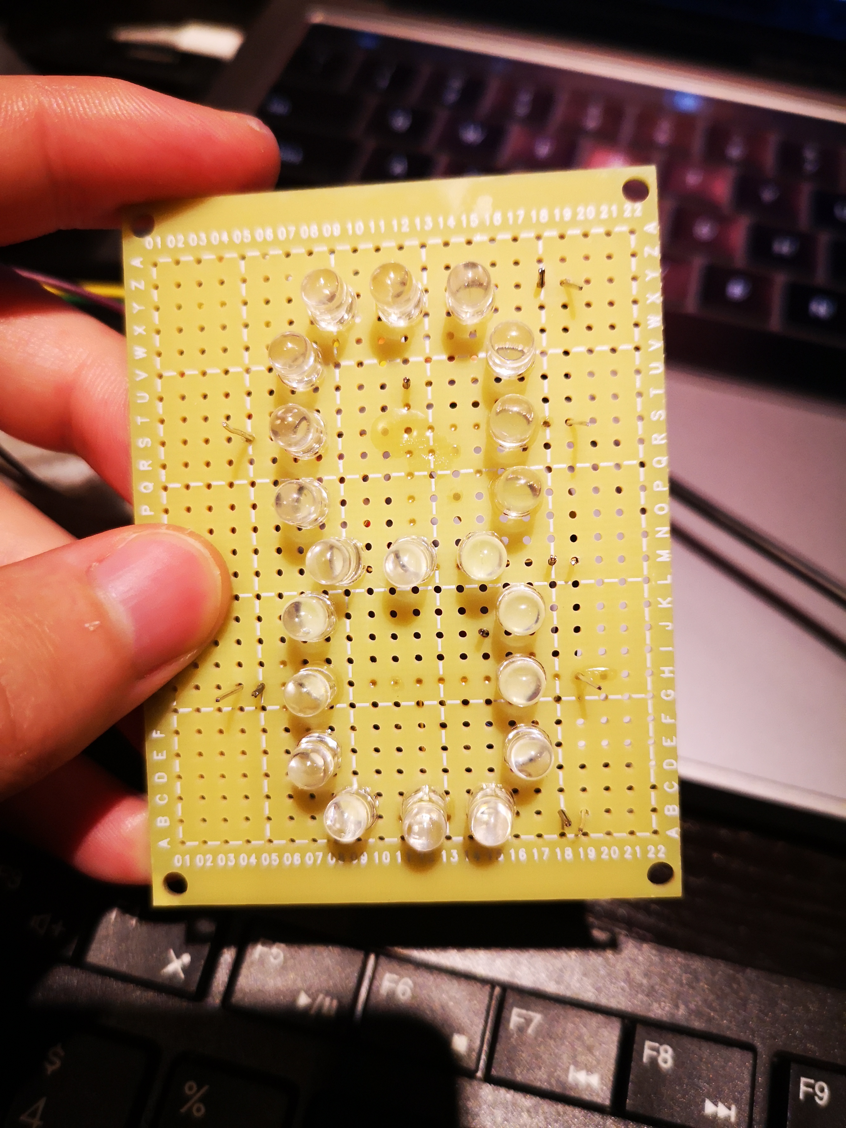
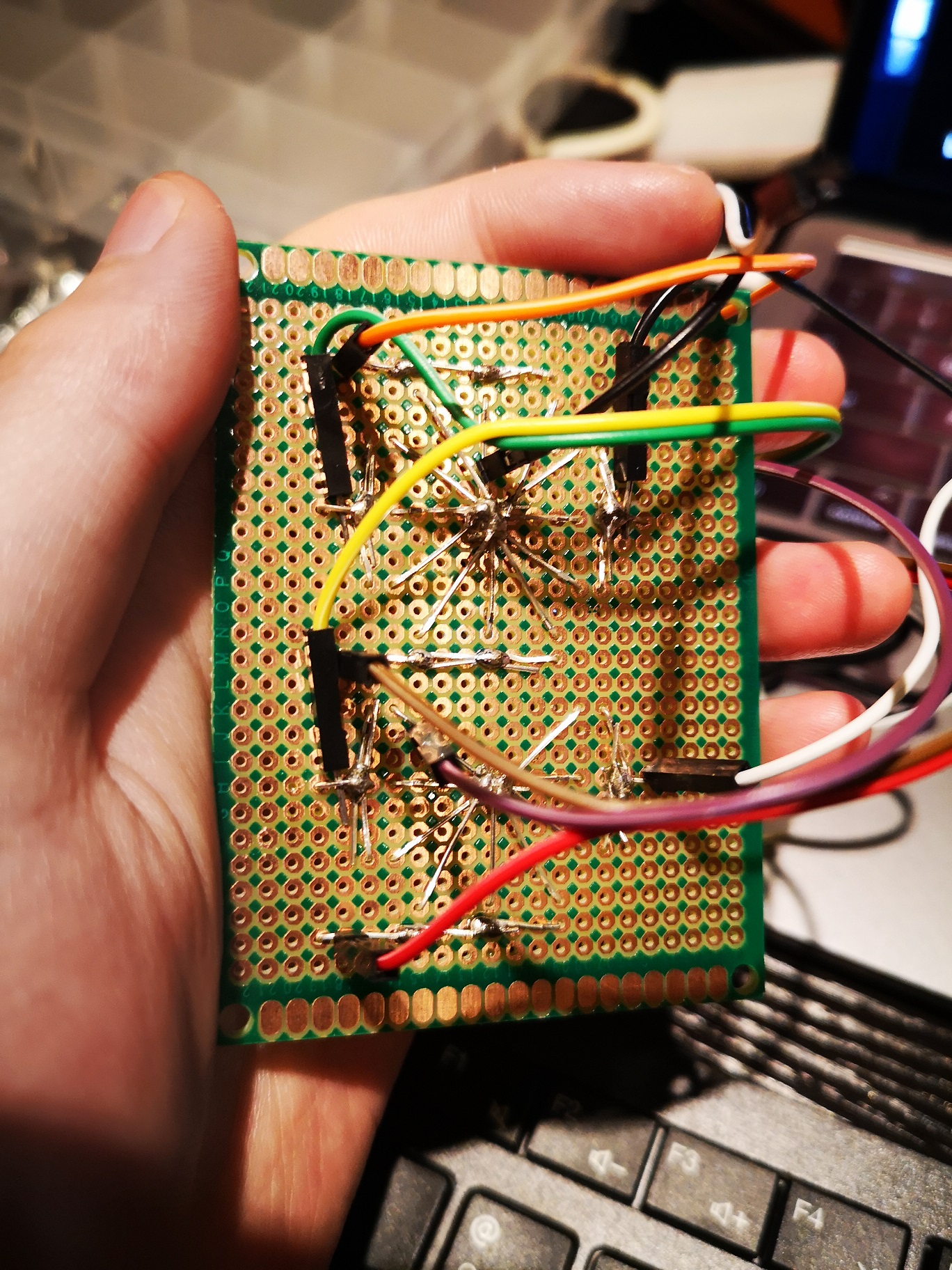
Each segment is formed by 3 LEDs in parallel. The 7 segments are attached to the GPIO ports on the Raspberry, which can produce a voltage difference on the LEDs. As shown in the picture, there are two common grounds to reduce soldering points.
Since we know current in a diode can only flow from anode to cathode. One LED doesn’t work because it is placed in the wrong direction. This has been fixed but I haven’t got time to film it.
I will post the updates after I solder the “thru hold socket” onto the board, which should make the whole thing more stable and reliable.
0 Comments